| Ch 10. Open-Channel Flow | Multimedia Engineering Fluids | ||||||
|
Uniform Flow |
Gradually Varied Flow |
Rapidly Varied Flow |
|||||
| Gradually Varied Flow | Case Intro | Theory | Case Solution |
| Chapter |
| 1. Basics |
| 2. Fluid Statics |
| 3. Kinematics |
| 4. Laws (Integral) |
| 5. Laws (Diff.) |
| 6. Modeling/Similitude |
| 7. Inviscid |
| 8. Viscous |
| 9. External Flow |
| 10. Open-Channel |
| Appendix |
| Basic Math |
| Units |
| Basic Fluid Eqs |
| Water/Air Tables |
| Sections |
| eBooks |
| Dynamics |
| Fluids |
| Math |
| Mechanics |
| Statics |
| Thermodynamics |
| ©Kurt Gramoll |
| |
|||||||||||||||||||||||||||||||||||||||||||||||
In this section, the equations for gradually varied open-channel flow will be discussed, and different possible profiles of the water surface will be presented. The direct step method is introduced to determine the water surface profile. |
|||||||||||||||||||||||||||||||||||||||||||||||
| Gradually Varied Flow Equation |
|||||||||||||||||||||||||||||||||||||||||||||||
For nonuniform open-channel flow, the cross sectional area, depth, and velocity vary along the channel. The flow is classified as gradually varied flow when the change of the fluid depth along the channel dy/dx is much less than one. For gradually varied flow, the channel can be divided into different sections called reaches, and the uniform flow equations, such as the Chezy and Manning equations, are applicable for calculating head losses in such reaches. |
|||||||||||||||||||||||||||||||||||||||||||||||
 Gradually Varied Flow |
For steady and one-dimensional flow, the equation for gradually varied
flow, based on the energy equation, can be written as The equation above can also be rewritten in terms of the change of the
water surface elevation and Froude number (Fr) as follows: For uniform flow, So is the same as Sf, hence the water surface elevation stays constant. On the other hand, for gradually varied flow, So does not equal Sf, and the water surface elevation can either increase or decrease in the direction of flow, depending on the type of profile. The slope of the energy grade line Sf can be determined from the Manning equation using the local value of fluid depth: |
||||||||||||||||||||||||||||||||||||||||||||||
| Water Surface Profiles |
|||||||||||||||||||||||||||||||||||||||||||||||
|
|
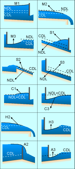
According to Eqn. 2, different water surface profiles can be derived, and there are altogether 12 possible shapes, as shown in the table and figure. The surface profiles can be classified into 5 categories according to the channel bed slopes. They include mild (M), steep (S), critical (C), horizontal (H) and adverse (A) slopes. The surface profiles can be further divided into different types according to its depth relative to the channel's normal depth (yo) and critical depth (yc). Table: Water Surface Profiles
|
||||||||||||||||||||||||||||||||||||||||||||||
| Direct Step Method |
|||||||||||||||||||||||||||||||||||||||||||||||
Note that equations
1 and 2 are nonlinear differential equations, and analytical solutions
are
possible
only for a
few problems. Hence numerical methods are necessary to
approximate the solutions. One of the simplest numerical methods is the
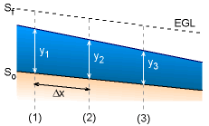
finite difference method. Eqn. 1 can be discretized as follows: where The direct step method starts from a boundary condition or control point (i.e., a point where the water surface elevation is given), and proceeds by assuming a surface elevation (y) and computing the distance Δx to the assumed elevation: |
|||||||||||||||||||||||||||||||||||||||||||||||
 [3]
[3]